Date Subject Software System
28th October 2025 CAD Tutorial FreeCAD 1.0.1 Windows 11

FreeCAD: Make a smooth body shape from section data

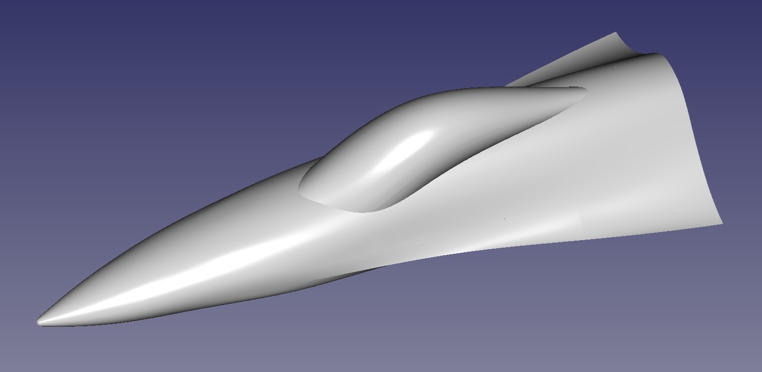
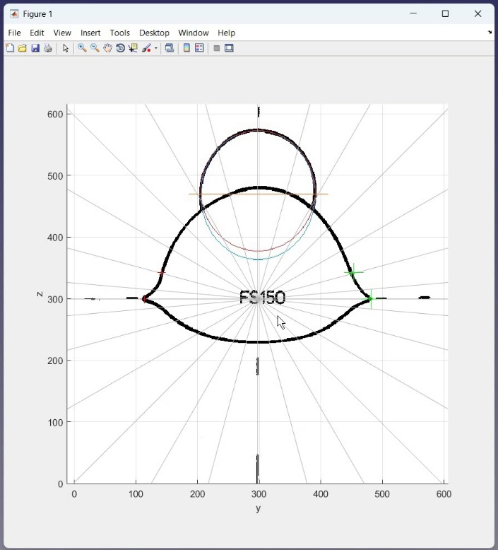
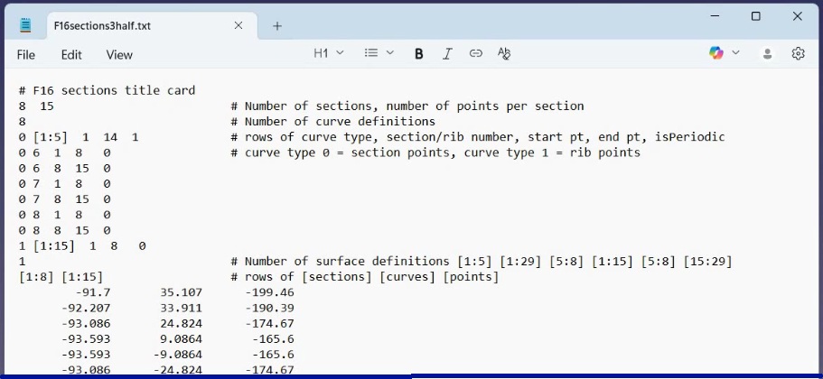
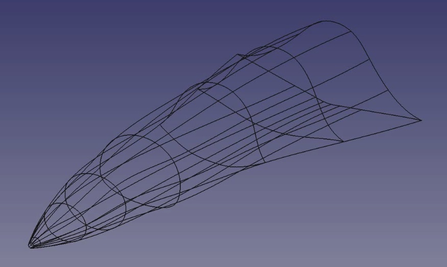
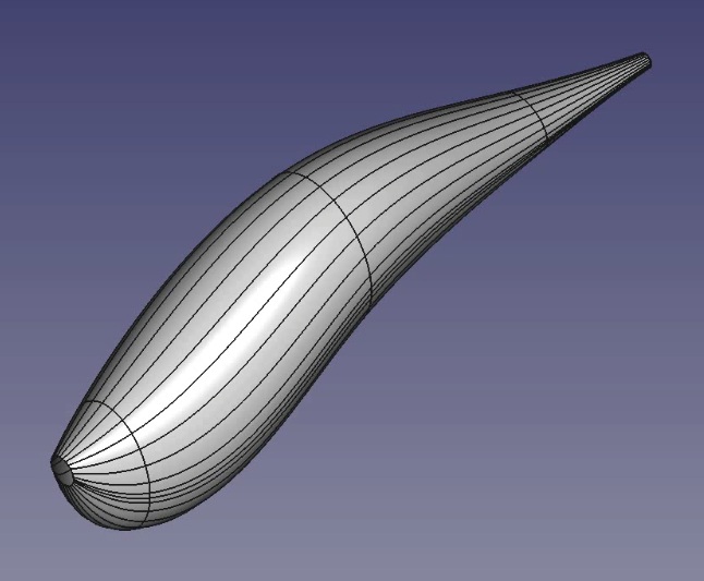
This article shows how to make smooth body surfaces in FreeCAD from section coordinates in a file.

See the later video for further examples.

Description

Intro: This method uses a macro to load section data from a text file and use this to create bspline curves and surface patches. The example here is for the forebody of an F16 aircraft as shown below.

There is also a youtube video accompanying this description (embedded at the end of this page).

The macro, section data and a freecad file containing the final shape are also available to download from the link in the footer.

If you have any comments or questions, please feel free to leave them at my youTube channel after the video for this tutorial.

F16 forebody shape

Freecad version: I'm now using Freecad version 1.0.1 and I'm running on Windows, although the macro has also been tested on FreeCAD 0.18 on Ubuntu 20.04 LTS.
Preparing the data: All the work is done in the creation of the input file.

For this example, I used Matlab to digitise the F16 forebody sections and collect data points for the input file.

I digitise the canopy by fitting the best fit ellipse through the canopy sections as shown on the image below.

Then I digitise the main body section without the canopy by drawing equally spaced radial lines and picking the intersection of these lines with the body shape. I take the average of left and right values as the drawing is not exactly symmetric.

File format: A typical file format is as follows:

This is the file for the main body section and has the following parts:

Line 1 is just a title - one and only one title line must be present

Line 2 gives number of sections and number of points per section

Line 3 gives the number of lines defining the curves - here 8

Lines 4-11 are the curve definitions. Curves are either type 0 (sections) or type 1 (ribs). The curves are defined by specifying which sections or ribs the curve should be created for, then specifying the start and end point of the curve. There must be curves for all points. No gaps between points are allowed.

Line 12 specifies the number of surface definitions to follow.

Line 13 specifies curves between all sections (1:8) and all ribs (1:15)

The remaining lines are the data points, 1 x y z point to a line

Input Files: The surfaces are made in two parts, so we have two input files. One is for the forebody shape, the other is for the canopy.

The macro script loads the data and creates the spline curves according to the input file definitions. The curves for the main body shape for this example are shown below.

The surface patches are then created as specified in the input file.

The patches for the canopy shape for this example are shown below.

If you turn off all the lines, you can see how smooth the surface patches are.
This is the end of this tutorial. There are other videos available or planned to further describe the script. There's also a video version of this tutorial below.

If you have any comments or questions, feel free to leave them at my youTube channel after the video for this tutorial.

Leave a Comment on this Article

Feel free to leave a comment or question. Include your email address if you want a private answer (email will not be shown). It takes a little while for the comment to appear as our AI bot checks for offensive or inappropriate comments!

We reserve the right to edit comments to remove unsuitable content.

Screen Name (displayed):
Email (not displayed):
Comment (<500 characters):

Video Walk-through of this Tutorial


Downloads

makePatches.zip